The Facts About Wedge Barriers Uncovered
Wedge Barriers Things To Know Before You Get This
Table of ContentsThe Buzz on Wedge BarriersThe 7-Second Trick For Wedge Barriers
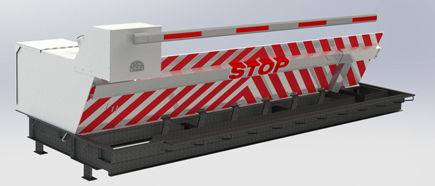
14 and the surface 12 to which the obstacle 10 is protected might be made from concrete - Wedge Barriers. 2, the barrier 10 is mounted to or includes an anchor or subframe (e. g., anchor 30 displayed in FIG. 2 )secured below the surface 12. For instance, the bather 10 may be bolted to the support or protected to the support by other mechanical fasteners. In the illustrated personification, the obstacle 10 includes a wedge plate 16, that includes a portion that is significantly parallel with the surface area 12 when the obstacle 10 is in the withdrawed placement. To put it simply, automobiles or people may pass over the obstacle 10 when the obstacle 10 is in the retracted position and experience minor elevation about the surface 12 while on the barrier 10. As discussed carefully listed below, when the barrier 10 remains in the deployed position, the wedge plate 16 is held and sustained in an elevated setting by a lifting device of the obstacle 10. Furthermore, the components 18 might be bolted or otherwise mechanically paired to each other. In this manner, repair service or substitute of several components 18 might be simplified and structured. That is, repair work or replacement of single parts
18 may be done quicker, easily, and expense successfully. FIG. In certain embodiments, the anchor 30 might be a steel frame including plates, light beams(e. g., I-beams ), and/or other structures that are safeguarded within the foundation 14, which might be concrete. At the surface area 12, a top side 28 of the support 30 may go to least partly subjected
, thereby making it possible for the attachment of the obstacle 10 to the anchor 30. g., threaded openings)in several light beams or plates of the anchor 30 may be revealed to the surface area 12. In this manner, screws 32 or this contact form various other mechanical fasteners might be utilized to secure the obstacle 10 to the support 30. As the barrier 10 is installed to the surface area 12 of the foundation 14, collection of particles and other product beneath the barrier may be reduced, and elements of the bather 10 might not be revealed to below quality settings. As indicated by recommendation character 52, the training mechanism 50 consists of components got rid of under the wedge plate 16. The elements 52 under the wedge plate 16 may include an electromechanical actuator, a web cam, one or more web cam surface areas, and so forth. Additionally, the lifting mechanism 50 includes a springtime setting up 54
The springtime pole 58 is paired to a web cam(e. g., camera 80 displayed in FIG. 4) of the training device 50. The springtimes 60 disposed about the spring rod 58 are kept in compression by springtime my sources sustains 62, consisting of a fixed spring assistance 64. That is, the set spring support 64 is dealt with loved one to the structure 14 and the remainder of the bather 10.
The Definitive Guide for Wedge Barriers
The continuing to be pressure applied to
the cam web cam deploy release wedge plate 16 may might provided given an electromechanical actuator 84 or other various other. The spring setting up 54 and the actuator 84(e. Wedge Barriers. g., electromechanical actuator)may operate together to convert the cam and raise the wedge plate 16.
As mentioned above, in the released position, the wedge plate 16 serves to obstruct accessibility or traveling beyond the obstacle 10. The obstacle 10(e. g., the wedge plate 16 )may obstruct anonymous pedestrians or vehicles from accessing a residential property or pathway. If a car is taking a trip in the direction of the deployed wedge plate 16(e. For example, in one situation, the safety and security legs 86 may be extended duringmaintenance of the barrier 10.